Configure New Embodiment in RoboTwin
We currently support the Aloha-AgileX, Franka, UR5, Piper, and ARX-X5 robot platforms. For usage instructions, see Configuation Tutorial.
Embodiments are stored in the assets/embodiments directory. Each embodiment follows this file structure:
# Using Franka as an example
- embodiments
  - franka-panda
    - config.yml # RoboTwin config file
    - curobo_tmp.yml # CuRobo config template
    - collision_franka.yml # CuRobo collision annotations
    - urdf_files/... # URDF files and corresponding GLB, STL files, etc.
This guide explains how to configure a new embodiment from scratch, using Franka as an example.
1. Step 1: Configure CuRobo Files
For complete configuration instructions, refer to the official documentation: https://curobo.org/tutorials/1_robot_configuration.html. This section provides the minimal configuration steps.
1.1 Create the embodiment directory and files
cd ${ROBOTWIN_ROOT_PATH}
mkdir -p assets/embodiments/new_robot
cd assets/embodiments/new_robot
touch curobo_tmp.yml
touch collision.yml
1.2 Configure curobo_tmp.yml
Here's a minimal Franka configuration example:
robot_cfg:
  kinematics:
    urdf_path: ${ASSETS_PATH}/assets/embodiments/franka-panda/panda.urdf
    base_link: "panda_link0"
    ee_link: "panda_hand"
    collision_link_names:
      [
        "panda_link0",
        "panda_link1",
        "panda_link2",
        "panda_link3",
        "panda_link4",
        "panda_link5",
        "panda_link6",
        "panda_link7",
        "panda_hand",
        "panda_leftfinger",
        "panda_rightfinger",
        "attached_object",
      ]
    collision_spheres: ${ASSETS_PATH}/assets/embodiments/franka-panda/collision_franka.yml
    collision_sphere_buffer: 0.004
    self_collision_ignore: {...}
    self_collision_buffer: {...}
    mesh_link_names: [...]
    lock_joints: {"panda_finger_joint1": 0.04, "panda_finger_joint2": 0.04}
    cspace:
      joint_names: ["panda_joint1","panda_joint2","panda_joint3","panda_joint4", "panda_joint5", "panda_joint6","panda_joint7","panda_finger_joint1", "panda_finger_joint2"]
      retract_config: [0.2200, -1.4012, -0.0406, -1.4901,  0.3050,  0.4521,  0.2099, 0.04, 0.04]
      null_space_weight: [1,1,1,1,1,1,1,1,1]
      cspace_distance_weight: [1,1,1,1,1,1,1,1,1]
      max_acceleration: 15.0
      max_jerk: 500.0
planner:
  frame_bias: [0., 0., 0.]
Key Parameter Explanations:
-
Path Requirements: Since this is a config template and CuRobo only supports absolute paths, both
urdf_pathandcollision_spheresmust keep the${ASSETS_PATH}/assets/embodiments/prefix unchanged. The${ASSETS_PATH}variable will be automatically replaced with the absolute path during subsequent operations. -
base_link and ee_link: These are the two most important links that directly determine your planning space. Replace these with your robot arm's actual link names.
-
Collision Configuration:
collision_link_namesandcollision_spheresdetermine self-collision and environment collision detection during planning. For detailed configuration, refer to the "Robot Collision Representation" section at https://curobo.org/tutorials/1_robot_configuration.html. All configurations in this repository are based on Isaac Sim 4.2. -
Joint Configuration:
cspace/joint_namesdirectly determines which joints need planning. This is defined by the URDF and must match the corresponding joint names. The lengths ofretract_config,null_space_weight, andcspace_distance_weightmust match the length ofjoint_names. -
Frame Bias: For single-arm URDFs, keep
planner/frame_biasas[0., 0., 0.]. For dual-arm setups like ALOHA, slight adjustments are needed (detailed in the dual-arm configuration section).
1.3 Configure collision.yml
After annotating with Isaac Sim, you'll get collision spheres for different joints. Fill them into collision.yml in this format:
collision_spheres:
    panda_link0:
        - "center": [0.0, 0.0, 0.085]
          "radius": 0.03
        # ... more spheres
    panda_link1:
        - "center": [0.0, -0.08, 0.0]
          "radius": 0.035
        # ... more spheres
1.4 Verify CuRobo Configuration
After configuring CuRobo, verify the setup with a simple forward kinematics test. First, update the ${ASSETS_PATH}:
cd ${ROBOTWIN_ROOT_PATH}
python script/update_embodiment_config_path.py
This will generate curobo.yml from curobo_tmp.yml. Then run this verification code:
import torch
from curobo.cuda_robot_model.cuda_robot_model import CudaRobotModel, CudaRobotModelConfig
from curobo.types.base import TensorDeviceType
from curobo.types.robot import RobotConfig
from curobo.util_file import get_robot_path, join_path, load_yaml

tensor_args = TensorDeviceType()

# Modify to the absolute path of `curobo.yml`
config_file = load_yaml("/abs_path/to/curobo.yml")

urdf_file = config_file["robot_cfg"]["kinematics"]["urdf_path"]
base_link = config_file["robot_cfg"]["kinematics"]["base_link"]
ee_link = config_file["robot_cfg"]["kinematics"]["ee_link"]
robot_cfg = RobotConfig.from_basic(urdf_file, base_link, ee_link, tensor_args)
kin_model = CudaRobotModel(robot_cfg.kinematics)
q = torch.rand((10, kin_model.get_dof()), **(tensor_args.as_torch_dict()))
out = kin_model.get_state(q)
If no errors occur, the configuration is successful.
2. Step 2: Configure RoboTwin Config File
2.1 Create config.yml
cd assets/embodiments/new_robot
touch config.yml
2.2 Parameter Configuration
Here's a Franka configuration example with detailed explanations:
urdf_path: "./panda.urdf"
srdf_path: "./panda.srdf"
joint_stiffness: 1000
joint_damping: 200
gripper_stiffness: 1000
gripper_damping: 200
move_group: ["panda_hand","panda_hand"]
ee_joints: ["panda_hand_joint","panda_hand_joint"]
arm_joints_name: [['panda_joint1', 'panda_joint2', 'panda_joint3', 'panda_joint4', 'panda_joint5', 'panda_joint6', 'panda_joint7'],
                  ['panda_joint1', 'panda_joint2', 'panda_joint3', 'panda_joint4', 'panda_joint5', 'panda_joint6', 'panda_joint7']]
gripper_name:
  - base: "panda_finger_joint1"
    mimic: [["panda_finger_joint2", 1., 0.]]
  - base: "panda_finger_joint1"
    mimic: [["panda_finger_joint2", 1., 0.]]
gripper_bias: 0.08
gripper_scale: [0.0, 0.04]
homestate: [[0, 0.19634954084936207, 0.0, -2.617993877991494, 0.0, 2.941592653589793, 0.7853981633974483],
            [0, 0.19634954084936207, 0.0, -2.617993877991494, 0.0, 2.941592653589793, 0.7853981633974483]]
delta_matrix: [[0,0,1],[0,-1,0],[1,0,0]]
global_trans_matrix: [[1,0,0],[0,-1,0],[0,0,-1]]
robot_pose: [[0, -0.65, 0.75, 0.707, 0, 0, 0.707],
             [0, -0.65, 0.75, 0.707, 0, 0, 0.707]]
planner: "curobo"
dual_arm: False
rotate_lim: [0.1, 0.8]
grasp_perfect_direction: ['right', 'left']
static_camera_list:
- name: head_camera
  position: [0.0, 0.8, 0.9]
  forward: [0, -1, 0]
  left: [1, 0, 0]
Parameter Explanations for New Embodiments:
-
urdf_path and srdf_path: Relative paths to URDF and SRDF files within
assets/embodiments/new_robot. These are loaded by Sapien into the simulator and directly determine the physical collision properties. -
move_group: Used by MPLib, equivalent to CuRobo's
ee_link. This is a list containing the ee_links for left and right arms. -
ee_joints: Since Sapien only supports global pose reading for joints, use the parent joint of the link specified in
move_group. -
arm_joints_name: Joint names, same as CuRobo's
joint_namesparameter, but organized as a 2D list containing joint names for both left and right arms. -
gripper_name: Controls gripper movement with structure:
list[dict{"base":str, "mimic":[[str, float, float], ...]}, dict{"base":str, "mimic":[[str, float, float], ...]}] - First level list represents left and right grippers
- Second level dict distinguishes "base" (actively controlled joint) and "mimic" (passive joints)
- "base": String representing any gripper finger, controlled by
gripper_scalewheregripper_scale[0]is closed state andgripper_scale[1]is open state -
"mimic": 2D array where each element contains [str, float1, float2] - joint name, scale, and bias. Joint angle = float1 * base_joint + bias
-
gripper_bias: Adjusts distance from
ee_jointto gripper center. For example, in vertical downward grasping, larger values move the gripper down, smaller values move it up. -
homestate: Initial robot arm state. Set carefully to avoid self-collision that could cause planning failures.
-
delta_matrix: Rotation matrix to unify different ee_joint coordinate systems. To avoid errors, initially use an identity matrix as placeholder:
[[1,0,0],[0,1,0],[0,0,1]]. -
global_trans_matrix: Rotation matrix to unify ee_joint pose reading in Sapien. To avoid errors, initially use an identity matrix as placeholder:
[[1,0,0],[0,1,0],[0,0,1]]. -
robot_pose: Base_link placement positions in format
[[x,y,z,qw,qx,qy,qz],[x,y,z,qw,qx,qy,qz]]. The x-coordinate represents the center position between two arms, recommended as 0. Actual spacing is adjusted in task configs likedemo_randomized.yml. -
dual_arm: Boolean indicating whether the URDF is dual-arm (true for ALOHA) or single-arm (false for Franka).
-
static_camera_list: Adjusts head_camera position, where
forwardandleftrepresent the z-axis and x-axis directions of the camera coordinate system.
3. Step 3: Add Embodiment Path
Edit task_config/_embodiment_config.yml and add your new robot path:
new_robot:
  file_path: "./assets/embodiments/new_robot"
Note: Your config.yml and curobo_tmp.yml must be directly located under file_path.
4. Step 4: Modify Task Config
In your task config (e.g., task_config/demo_randomized.yml), change the embodiment section to:
embodiment:
- new_robot
- new_robot
- 0.8  # Distance between the two robot arms
5. Step 5: Calibrate delta_matrix
This calibration requires the desktop environment and is extremely important.
5.1 Create Temporary URDF
Before calibrating delta_matrix and global_trans_matrix, you must create a temporary URDF. Using Franka as an example:
cd assets/embodiments/franka-panda
cp panda.urdf panda.urdf.save
Modify panda.urdf by: 1. Remove or comment out all collision tags for every link 2. Remove all joint limits and change all revolute joints to continuous
Example modifications:
<!-- Comment out collision -->
<link name="panda_link1">
    <visual>
      <geometry>
        <mesh filename="franka_description/meshes/visual/link1.glb"/>
      </geometry>
    </visual>
    <!-- <collision>
      <geometry>
        <mesh filename="franka_description/meshes/collision/link1.stl"/>
      </geometry>
    </collision> -->
</link>

<!-- Remove joint limits, change revolute to continuous -->
<!-- <joint name="panda_joint3" type="revolute"> -->
<joint name="panda_joint3" type="continuous">
    <origin rpy="1.57079632679 0 0" xyz="0 -0.316 0"/>
    <parent link="panda_link2"/>
    <child link="panda_link3"/>
    <axis xyz="0 0 1"/>
    <!-- Remove this line: <limit effort="87" lower="-2.8973" upper="2.8973" velocity="2.1750"/> -->
</joint>
5.2 Find Valid Pose
The delta_matrix unifies coordinate systems across different robot arms. First, run this script to find a valid pose:
import torch
from curobo.types.base import TensorDeviceType
from curobo.types.math import Pose
from curobo.types.robot import RobotConfig
from curobo.util_file import get_robot_configs_path, join_path, load_yaml
from curobo.wrap.reacher.ik_solver import IKSolver, IKSolverConfig

tensor_args = TensorDeviceType()
config_file = load_yaml(join_path(get_robot_configs_path(), "franka.yml"))
urdf_file = config_file["robot_cfg"]["kinematics"]["urdf_path"]
base_link = config_file["robot_cfg"]["kinematics"]["base_link"]
ee_link = config_file["robot_cfg"]["kinematics"]["ee_link"]
robot_cfg = RobotConfig.from_basic(urdf_file, base_link, ee_link, tensor_args)

ik_config = IKSolverConfig.load_from_robot_config(
    robot_cfg,
    None,
    num_seeds=20,
    self_collision_check=False,
    self_collision_opt=False,
    tensor_args=tensor_args,
    use_cuda_graph=True,
)
ik_solver = IKSolver(ik_config)
x_values = torch.linspace(0.35, 0.0, 25).tolist() + torch.linspace(0.35, 0.7, 25).tolist()
y_values = torch.linspace(0.25, 0.0, 25).tolist() + torch.linspace(0.25, 0.5, 25).tolist()
z_values = torch.linspace(0.25, 0.0, 25).tolist() + torch.linspace(0.25, 0.5, 25).tolist()
quaternion = torch.tensor([[1.0, 0.0, 0.0, 0.0]], device='cuda:0')

print("Testing IK solutions for different positions:")
print("x, y, z, success")
for x in x_values:
    for y in y_values:
        for z in z_values:
            goal = Pose(
                position=torch.tensor([[float(x), float(y), float(z)]], device='cuda:0'),
                quaternion=quaternion
            )
            result = ik_solver.solve_single(goal)
            if result.success.item() == True:
                print(f"{x:.2f}, {y:.2f}, {z:.2f}, {result.success}")
Expected output:
x, y, z, success
0.35, 0.23, 0.09, tensor([[True]], device='cuda:0')
0.35, 0.23, 0.08, tensor([[True]], device='cuda:0')
0.35, 0.23, 0.07, tensor([[True]], device='cuda:0')
...
5.3 Test in Simulation
Choose any successful xyz coordinates and modify envs/robot/planner.py around line 126:
## Temporarily add the successful xyz coordinates ##
target_pose_p = [0.35, 0.23, 0.09]  # Example: using 0.35, 0.23, 0.09
target_pose_q = [1., 0., 0., 0.]
## End temporary addition ##
goal_pose_of_gripper = CuroboPose.from_list(list(target_pose_p) + list(target_pose_q))
Modify envs/beat_block_hammer.py to add a temporary test:
######## Add temporary test ##########
arm_tag = ArmTag('left')
action = Action(arm_tag, 'move', [-0.05,0.,0.9])
self.move((arm_tag, [action]))
time.sleep(100)
######################################
# Grasp the hammer with the selected arm
self.move(self.grasp_actor(self.hammer, arm_tag=arm_tag, pre_grasp_dis=0.12, grasp_dis=0.01, gripper_pos=0.35))
Set render_freq to a positive number in your task config (e.g., demo_randomized.yml), then run:
bash collect_data.sh beat_block_hammer demo_randomized 0
5.4 Analyze Coordinate Systems
You should see a visualization similar to this:
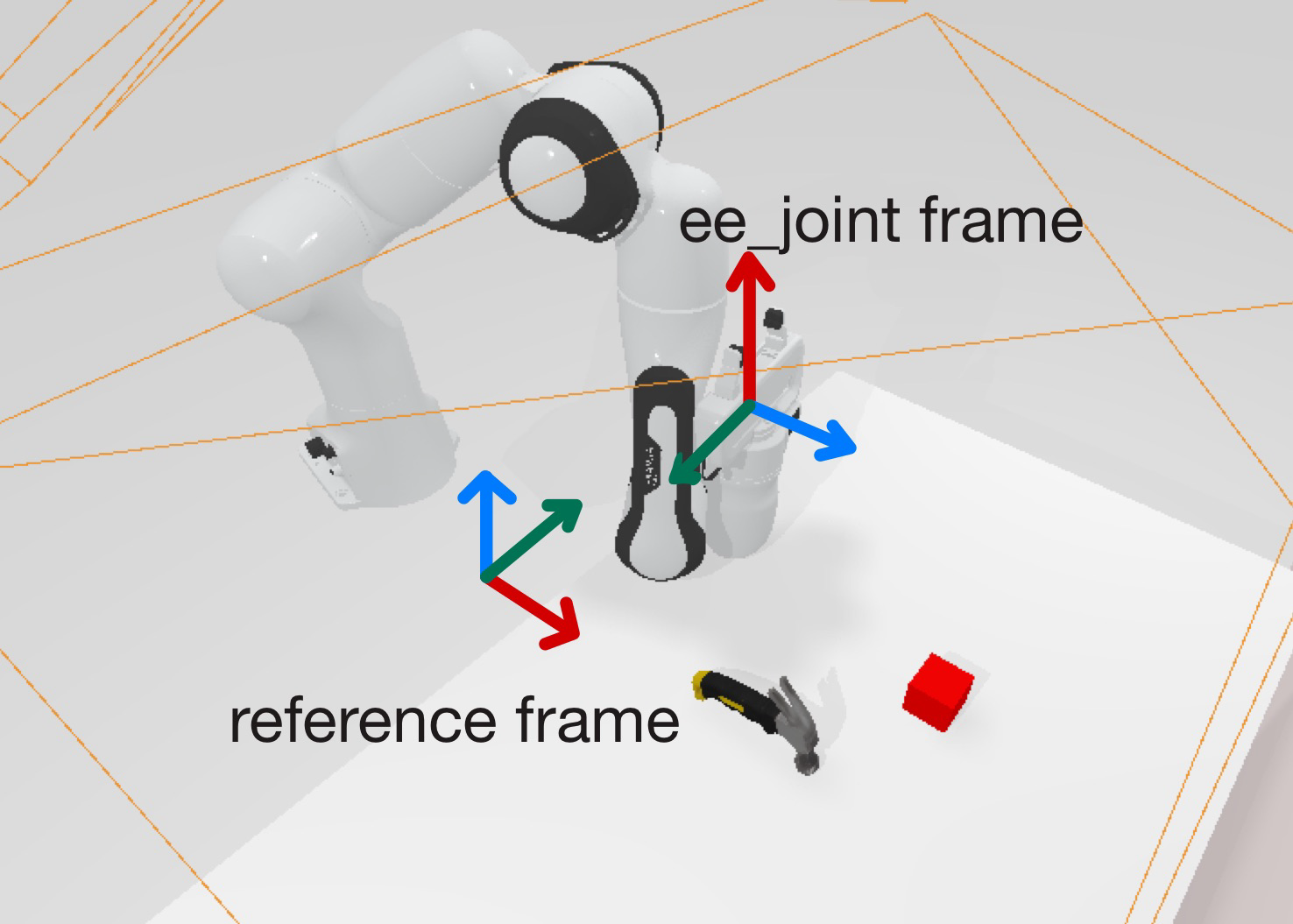
Coordinate System Analysis: - ee_joint_frame: - X-axis (red): Should point from the link toward the gripper direction - Y-axis (green): Should be parallel to gripper movement direction (positive or negative) - Z-axis (blue): Determined by right-hand rule
- reference_frame:
- X-axis: Robot's forward direction
- Z-axis: Opposite to gravity direction (upward)
- Y-axis: Determined by right-hand rule
- This frame is fixed and consistent across all robots
5.5 Calculate delta_matrix
The delta_matrix represents the rotation from ee_joint frame to reference frame: {ee_joint}_Rotation_{reference}.
From the example image above, the delta_matrix would be:
delta_matrix = [[0, 0, 1],
                [0, -1, 0],
                [1, 0, 0]]
Update this matrix in your config.yml.
6. Step 6: Calibrate global_trans_matrix
6.1 Get Actual Planned Pose
Keep the time.sleep in beat_block_hammer.py and modify envs/robot/planner.py to output the target quaternion:
target_pose_p[0] += self.frame_bias[0]
target_pose_p[1] += self.frame_bias[1]
target_pose_p[2] += self.frame_bias[2]
# Remove the hardcoded position and quaternion
# target_pose_p = np.array([0.35, 0.23, 0.09])
# target_pose_q = np.array([1.0, 0.0, 0.0, 0.0])
print('[debug]: target_pose_q: ', target_pose_q)
goal_pose_of_gripper = CuroboPose.from_list(list(target_pose_p) + list(target_pose_q))
Expected output:
[debug]: target_pose_q: [ 1.68244557e-03 -9.98540531e-01 -3.19133105e-04 -5.39803316e-02]
Important: Use your actual output quaternion values, not the example above. Each robot arm will produce different quaternion values based on its specific configuration.
6.2 Test with New Quaternion
Use the output quaternion to test valid positions by modifying the test script, and REMEMBER TO UPDATE THE QUATERNION:
import torch
from curobo.types.base import TensorDeviceType
from curobo.types.math import Pose
from curobo.types.robot import RobotConfig
from curobo.util_file import get_robot_configs_path, join_path, load_yaml
from curobo.wrap.reacher.ik_solver import IKSolver, IKSolverConfig

tensor_args = TensorDeviceType()
config_file = load_yaml(join_path(get_robot_configs_path(), "franka.yml"))
urdf_file = config_file["robot_cfg"]["kinematics"]["urdf_path"]
base_link = config_file["robot_cfg"]["kinematics"]["base_link"]
ee_link = config_file["robot_cfg"]["kinematics"]["ee_link"]
robot_cfg = RobotConfig.from_basic(urdf_file, base_link, ee_link, tensor_args)

ik_config = IKSolverConfig.load_from_robot_config(
    robot_cfg,
    None,
    num_seeds=20,
    self_collision_check=False,
    self_collision_opt=False,
    tensor_args=tensor_args,
    use_cuda_graph=True,
)
ik_solver = IKSolver(ik_config)
x_values = torch.linspace(0.35, 0.0, 25).tolist() + torch.linspace(0.35, 0.7, 25).tolist()
y_values = torch.linspace(0.25, 0.0, 25).tolist() + torch.linspace(0.25, 0.5, 25).tolist()
z_values = torch.linspace(0.25, 0.0, 25).tolist() + torch.linspace(0.25, 0.5, 25).tolist()

###### REMEMBER TO UPDATE THE QUATERNION ####
#############################################
# Update the quaternion from the debug output
quaternion = torch.tensor([[1.68244557e-03, -9.98540531e-01, -3.19133105e-04, -5.39803316e-02]], device='cuda:0')
#############################################

print("Testing IK solutions for different positions:")
print("x, y, z, success")
for x in x_values:
    for y in y_values:
        for z in z_values:
            goal = Pose(
                position=torch.tensor([[float(x), float(y), float(z)]], device='cuda:0'),
                quaternion=quaternion
            )
            result = ik_solver.solve_single(goal)
            if result.success.item() == True:
                print(f"{x:.2f}, {y:.2f}, {z:.2f}, {result.success}")
Expected output:
x, y, z, success
0.35, 0.24, 0.27, tensor([[True]], device='cuda:0')
0.35, 0.24, 0.28, tensor([[True]], device='cuda:0')
...
6.3 Calculate global_trans_matrix
Update envs/robot/planner.py with a successful position:
target_pose_p[0] += self.frame_bias[0]
target_pose_p[1] += self.frame_bias[1]
target_pose_p[2] += self.frame_bias[2]

# Update with successful position, remove debug print and target_pose_q
target_pose_p = np.array([0.35, 0.24, 0.27])
# target_pose_q = np.array([1.0, 0.0, 0.0, 0.0])
# print('[debug]: target_pose_q: ', target_pose_q)
goal_pose_of_gripper = CuroboPose.from_list(list(target_pose_p) + list(target_pose_q))
Replace the entire play_once(self) function in envs/beat_block_hammer.py and UPDATE THE DELTA_MATRIX BELOW:
def play_once(self):
    # Get the position of the block's functional point
    block_pose = self.block.get_functional_point(0, "pose").p
    # Use left arm for testing
    arm_tag = "left"

    arm_tag = ArmTag('left')
    action = Action(arm_tag, 'move', [-0.05,0.,0.9])
    self.move((arm_tag, [action]))

    import transforms3d as t3d
    while True:
        left_ee_global_pose_q = list(self.robot.left_ee.global_pose.q)
        w_R_joint = t3d.quaternions.quat2mat(left_ee_global_pose_q)
        w_R_aloha = t3d.quaternions.quat2mat(action[1][0].target_pose[3:])
        ######## REMEMBER TO UPDATE THE DELTA_MATRIX!!!! ####
        # Update this delta_matrix with your calculated value
        delta_matrix = np.matrix([[0,0,1],[0,-1,0],[1,0,0]])
        #####################################################
        global_trans_matrix = w_R_joint.T @ w_R_aloha @ delta_matrix.T
        print(np.round(global_trans_matrix))
Run the simulation again:
bash collect_data.sh beat_block_hammer demo_randomized 0
Expected output:
[[ 1.  0.  0.]
 [ 0. -1.  0.]
 [ 0. -0. -1.]]
This is your global_trans_matrix. Add it to your config.yml.
6.4 Clean Up
Restore the modified files:
git checkout -- envs/robot/planner.py
git checkout -- envs/beat_block_hammer.py
Congratulations! Your new embodiment configuration is now complete.
7. Dual-Arm URDF Configuration
Dual-arm URDFs have a slightly different structure:
# Using ALOHA as an example
- embodiments
  - aloha
    - config.yml # RoboTwin config file
    - curobo_left_tmp.yml # Left arm CuRobo config template
    - curobo_right_tmp.yml # Right arm CuRobo config template
    - collision_aloha_left.yml # Left arm collision annotations
    - collision_aloha_right.yml # Right arm collision annotations
    - urdf_files/... # URDF files and corresponding GLB, STL files, etc.
7.1 Key Considerations for Dual-Arm Setup:
-
Frame Bias Configuration: In
curobo_left_tmp.ymlandcurobo_right_tmp.yml, if your CuRobo config'srobot_cfg/kinematics/base_linkdoesn't match the URDF'sbase_link(e.g., usingfl_base_linkin ALOHA), you needplanner/frame_bias. This represents the translation vector from the URDF'sbase_linkto the CuRobo'sbase_link(e.g.,fl_base_link). The same applies to the right arm. -
Config.yml Settings: Set
dual_arm: Truein config.yml for dual-arm configurations.
This completes the embodiment configuration process. The setup allows RoboTwin to properly load and control your new robot embodiment in both simulation and planning contexts.